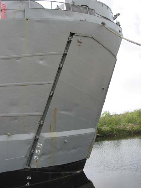
Bow Door and Ramp
BOW
DOOR EQUIPMENT:
Each
bow door is 24 feet high and 14'11" wide. The bow doors are handled by two 3-horsepower bow door drive units, each consisting of
a gear motor which drives a screw through open gearing.
This screw is engaged by means of a taper and wedge to a rack traveling
in a rack guide and mating with a segment made fast to the bow doors.
Motors are operated by means of push button stations marked “OPEN”,
“CLOSE” and “STOP”. Four of
these push buttons are provided per vessel, two for each motor.
Two limit switches are provided, one at either end of the travel of the
rack. These limit switches are
actuated by a switch stop. Adjustment
of these two limit switches must be made after assembly so as to provide for the
proper arc of travel of the bow doors. Clearance
is provided between the hub flanges of the screw gear, and the bedplate washers.
This clearance is such that when the doors are almost closed, and the bow
door limit switch has operated, the doors may be jacked together and locked by
means of turn-buckles. The limit
switch which operates to shut off the motor when the bow door closes should be
so set that after the door has come to rest it may be completely closed by means
of the above mentioned turn-buckles, making use of the clearance specified
previously.

Extreme
care must be taken during installation of the bow door equipment to insure that
the rack and rack guide are properly aligned with the bow door segment and that
the gear motor base is properly shimmed to correspond with this alignment.
If the rack guides are not sufficiently rigid, deflection will be
permitted and the screw may be so loaded as to cause severe deflection, unduly
increasing the load on the electric motor.
The
bow door equipment is designed for a rack thrust of 14,000 pounds at a rack
speed of 1.98 feet per minute. Care
should be taken that this equipment is not allowed to be operated at extreme
overload or without proper lubrication.
Bow Door Gear Motor: Pacific Gear & General Electric (motor, controller and wiring panel)
Bow Door & Ramp Gate Equipment:
Western Gear Works, Seattle, Washington
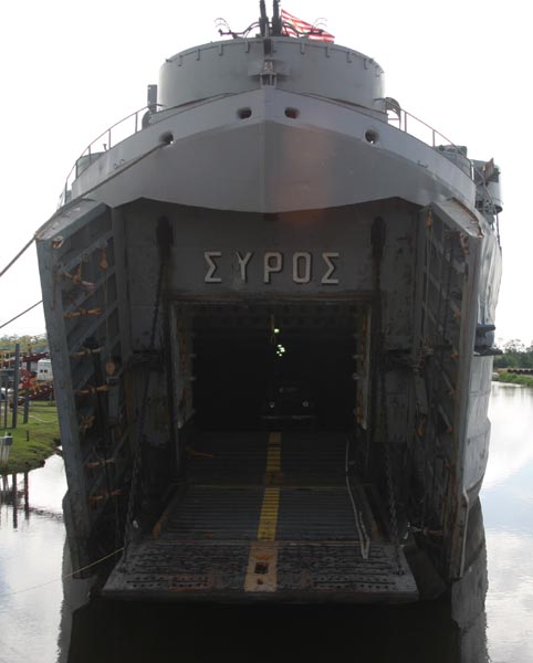
RAMP
GATE EQUIPMENT:
The
Bow ramp is 23 feet long and 16'3" wide. The actual opening into the
tank deck is 13 feet high and 15 foot wide. The ramp gate equipment consists primarily of a main shaft mounting two wildcats at
the extreme ends and driven through a double reduction set of spur gears by a
10-horsepower gear motor. The
equipment operates in both directions by means of push button stations marked,
“HOIST”, “LOWER” and “STOP”.
A
limit switch is provided which is operated by a sprocket of the low speed shaft
and which actuates the arm of a track type limit switch.
This limit switch is arranged to operate in the lower or open position of
the ramp gate only. An additional limit switch is provided which is to be mounted
so as to be operated by the ramp gate itself when being closed.
This limit switch is to operate in the upper or closed position of the
ramp gate only. The adjustment of
this limit stop should be made carefully so as to shut off the motor at the
proper time and prevent the ramp from damaging the ship structure.
The ramp gate gear motor is provided with regenerative braking in the
lowering direction, in order to prevent the ramp from lowering at excessive
speed.
The
ramp may also be lowered without the use of power by disengaging the sliding
pinion, and locking it in the disengaged position. Before do doing it is necessary that the hand brake wheel be
tightened in order to prevent the ramp from falling after the pinion is
disengaged. After release of this
pinion the ramp may be lowered by releasing the hand brake a sufficient amount
to permit the ramp to start to lower. Care
should be taken not to allow the ramp to fall at too great a speed.
When operating under these conditions it should be borne in mind that as
the ramp lowers, its load increases progressively and will be more difficult to
hold the nearer it approaches a horizontal position.
If
difficulty is experienced in engaging or disengaging the sliding pinion it may
be readily shifted by operating the hand release on the electric brake, at the
same time rotating the high speed gear slightly by hand, bringing the teeth of
the sliding pinion and the teeth of the low speed gear into alignment in order
that they may properly mesh.
If
one chain is tighter than the other during installation or if by some reason
excessive sag develops in one or the other of the chains, it may be brought back
into alignment by disengaging the coupling bolts and rotating the coupling in
the proper direction a sufficient amount to engage with the next set of holes,
thereby bringing the chain into the same tension.
This
ramp gate machinery is designed for a load on the chains of 17,250 pounds and a
speed of rotation of the wildcat shaft of 2.62 RPM. Care should be taken that this equipment is not allowed to be
operated at extreme overload or without proper lubrication.
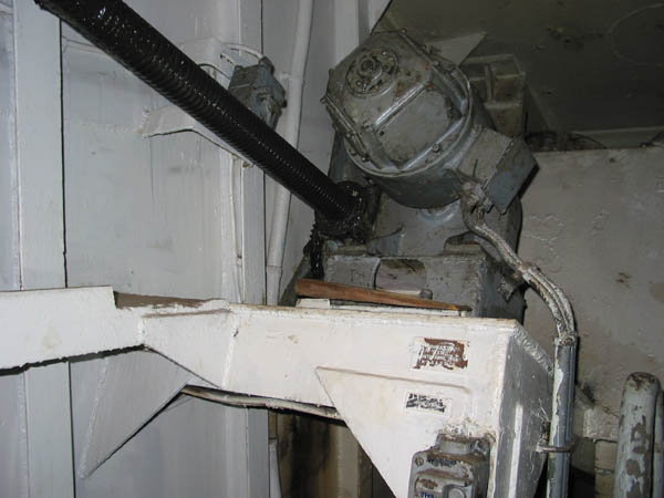
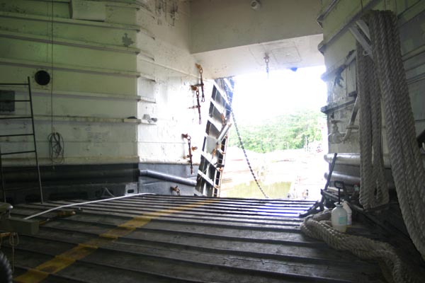
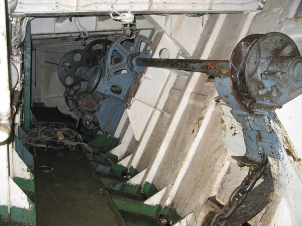 Ramp Gate Equipment aboard LST 325.
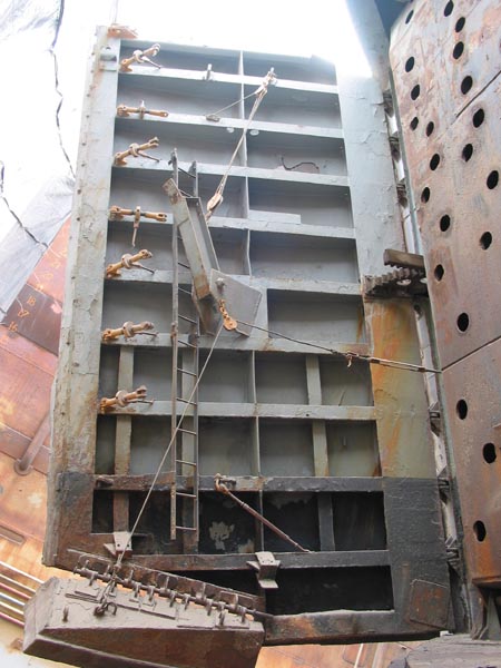
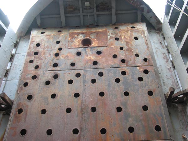 Ramp Gate secured in position.